In the design of MRI magnetic components, magnetic field intensity and uniformity are critical performance indicators. Through theoretical analysis and simulation modeling, the main factors influencing magnetic field performance can be summarized as follows:
1. Magnetization Pattern Design
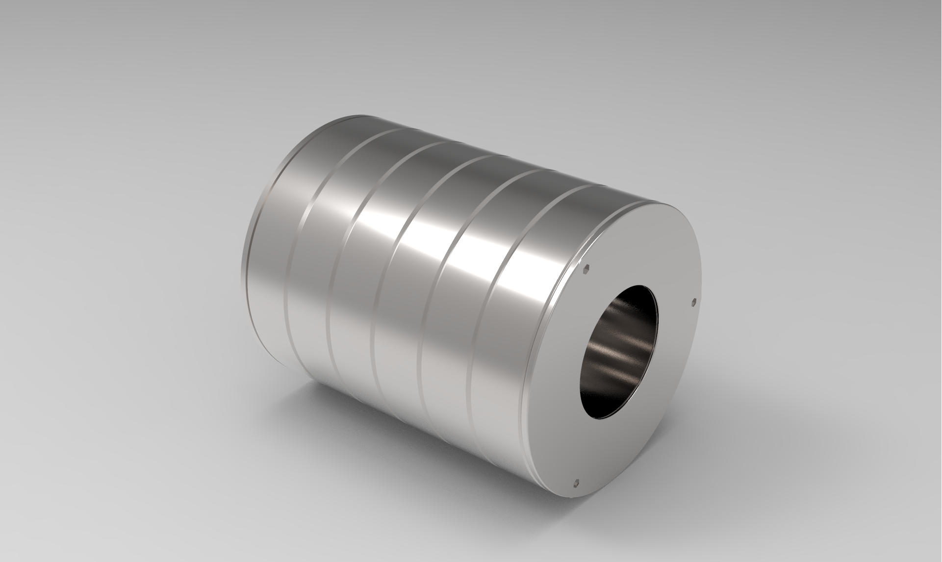
This component adopts an alternating N-S magnetization arrangement (see Figure 1). Although this layout results in slightly lower surface magnetic field compared to the traditional Halbach structure, it offers smoother magnetic field transitions, which is beneficial for field uniformity and control. A 12-segment magnet structure is used (Figure 2), confirmed by both simulation results and literature references. Future studies will compare this with a 16-segment structure through actual testing.
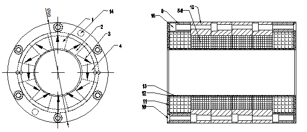
Figure 1
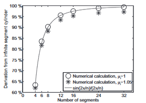
Figure 2
2. Magnet Size Design: Inner and Outer Diameter
The inner and outer diameters of the magnets significantly affect the magnetic field strength:
- A smaller inner diameterresults in a higher magnetic fieldand is the key parameter for tuning.
- While increasing the outer diameterimproves the magnetic field initially, the benefit diminishes beyond a certain point, and excessive size leads to material waste.
Hence, it’s advisable to follow the common magnet aspect ratio guideline: length/diameter > 0.5, preferably > 0.7, to strike a balance between performance and cost.
3. Magnet Height Effect
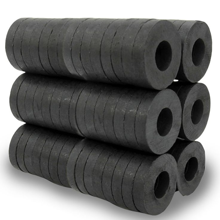
The magnet’s height influences both field intensity and uniformity. Due to manufacturing limitations, single magnets cannot reach the desired height, so a segmented stack structure is used to reinforce the design.
4. Magnet Performance and Stability
Considering the operating environment, magnets must exhibit stable thermal resistance. This design uses magnets rated for 100°C to ensure reliable long-term operation.
5. Magnetic Deviation Angle Control
Deviation in the magnetization angle (magnetic deviation angle) impacts field uniformity. Most magnets are charged at an angle, which demands high precision. We optimize the production process to control angular deviation within acceptable limits.
6. Assembly Gap Handling in Circular Magnet Arrays
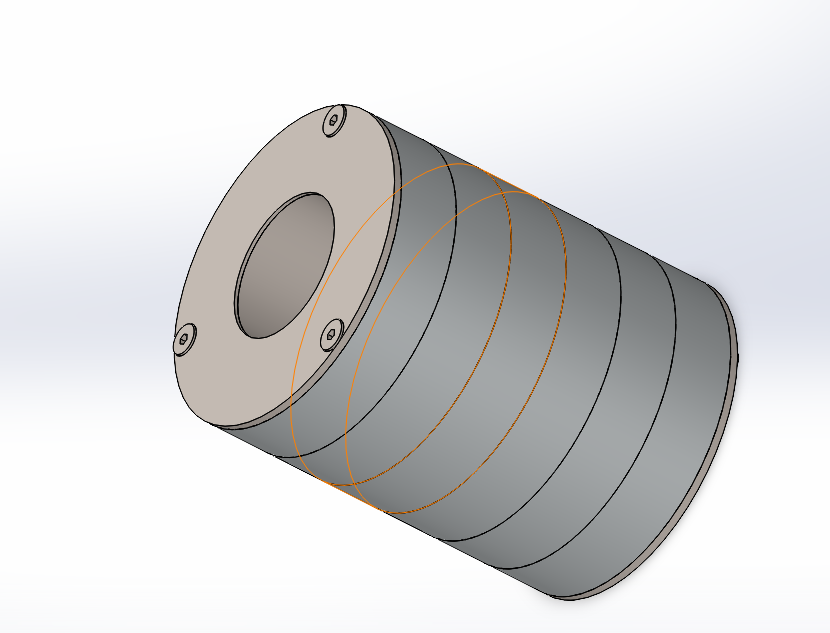
Each magnetic ring layer consists of 12 magnet segments arranged in a circle. The precision of these joints directly affects the magnetic field. To reduce cumulative error:
- We pair negative and positive tolerance magnetsfor better alignment.
- We strictly control angular deviationof each piece to minimize assembly errors.
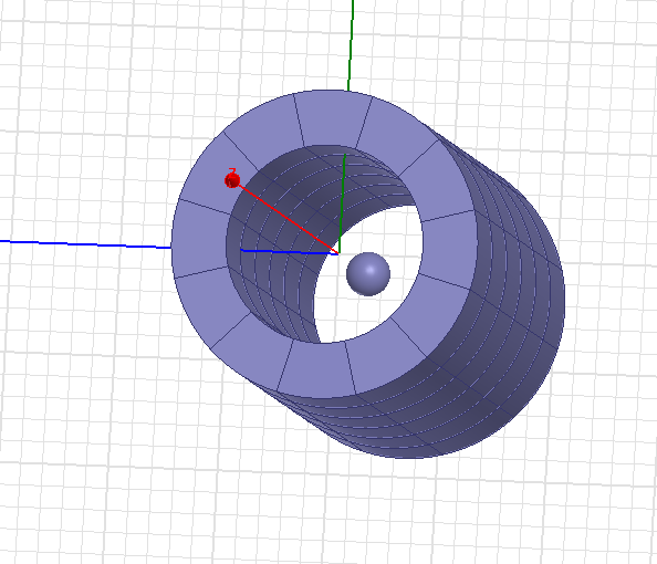
Surface Magnetic Field Simulation Image
3D Modeling Image
7. Stack Flatness Control
Uneven end surfaces in stacked magnet rings create installation gaps and harm magnetic field uniformity. We use grinding machines to process both end faces of the magnetic rings to ensure:
- Flat surfaces;
- Parallel end faces;
- Tight stacking integration.
8. Installation Angle and Center Axis Alignment
Precise alignment between magnetic rings is required to prevent directional misalignment, which can destabilize the field:
- Outer rings are designed with pre-set positioning pin holesto ensure consistent installation angles.
- The center axis field distributionis simulated (see Figure 3), and a 40mm marginis reserved in the design to keep magnetic field fluctuations within the target SR region (20mm) to a minimum.
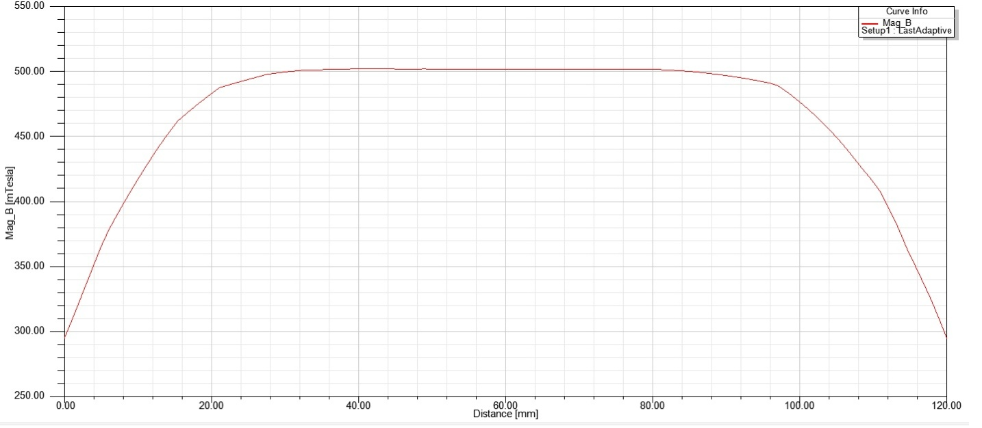
Figure 3
Reference Literature and Expansion Plans
Reference Journal: Journal of Applied Physics, Vol. 104, 013910, 2008
Article Title: Optimization and improvement of Halbach cylinder design
Authors: R. Bjørk, C. R. H. Bahl, A. Smith, N. Pryds
DOI: 10.1063/1.2952537
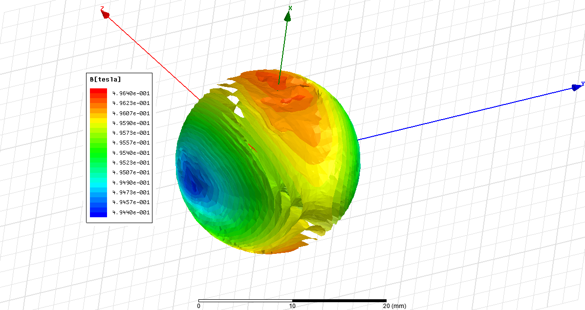
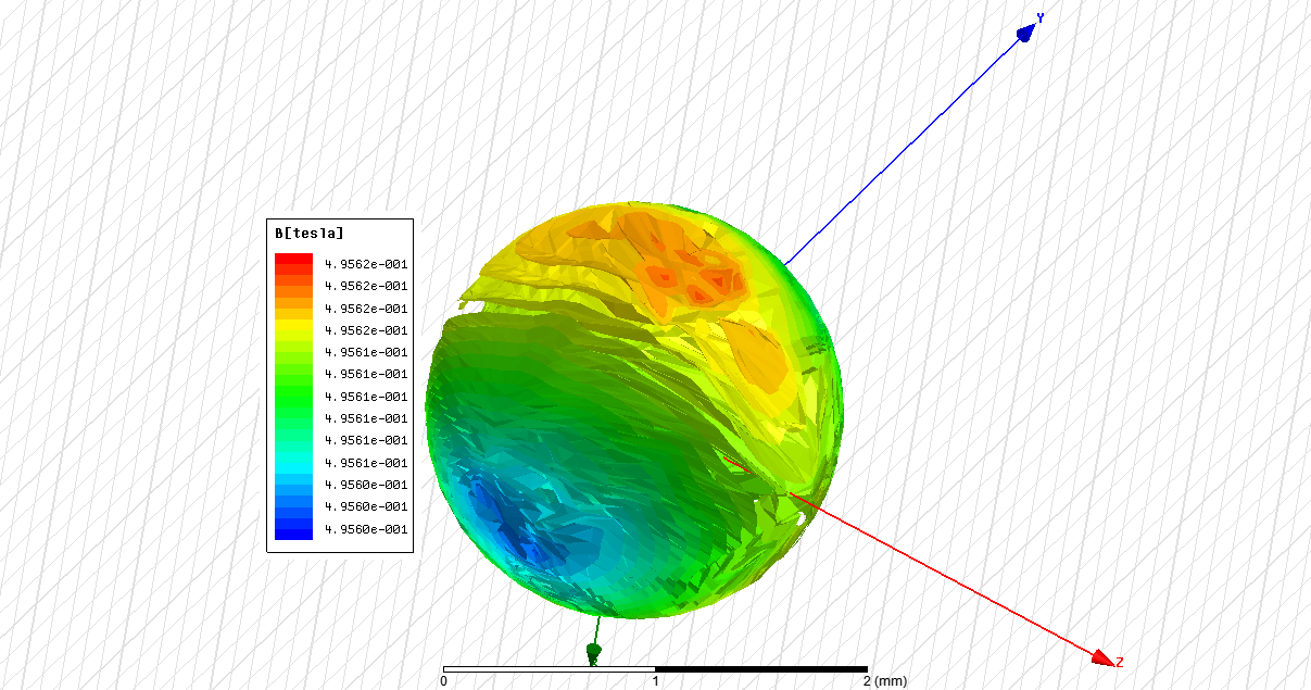
Theoretical vs. Measured Values (Unit: T / Gauss)
Region | Theoretical Value | Measured Value | Error Range |
SR10 | 0.4954T, ±20Gs | 0.4853T, ±46Gs | Well controlled, with slight room for improvement |
SR1 | 0.4956T, ±0.2Gs (≈40ppm) | 0.4853T, ±3Gs (≈618ppm) | Center stability needs further optimization |
SR10
SR1
Patents and Simulation Outcomes
This design is accompanied by related patent applications, and the complete magnetic field simulation and 3D structural modeling has been completed. The final step is physical prototype assembly and verification.
If you are interested in learning more about our MRI magnetic component R&D, simulation capabilities, or magnetic field optimization services, feel free to contact us for further discussion!
